In this article you will learn more about our methods for the development and design of Hardware-In-the-Loop (HIL) and Model-In-the-Loop (MIL) test benches. This document sums up overall experience of test bench creation gained by our engineers in several CS-25 certified aircrafts projects.
For your convenience, major topics are outlined below:
Modern onboard test benches are complex tools with high requirements both for integrity and flexibility that must not only function as equipment testers or testing devices (including certification tests) but also address aspects of test bench evolution. Before we proceed it is crucial to highlight some of the test bench design aspects:
Therefore, when designing a test bench, you need to understand that:
Provided that modern avionics normally have thousands of wires and hundreds of thousands of data exchange parameters it is obvious that test bench design should start with tools selection capable of seamless connection resulting in toolchain. Based on an iterative method, we came up with the following design approach and set of tools that allow to make test benches universal, modifiable and easily manageable:
If used properly, these three products can be integrated extensively to simplify most test bench design processes.
At the same time, there was no tool for developing avionics available on the market. As a result, based on our own experience and understanding of all challenges and aspects of designing complex systems, we independently developed dBricks, a universal tool that can be easily integrated with Simulink and ADS2R4.
dBricks tool is used for:
ADS2R4 is a real-time test and simulation environment specifically designed for development, test, integration, and validation tasks with architecture that fits both integrity and flexibility.
dBricks is a core tool that is used to streamline the complex development and integration of onboard equipment. The tool is a single database for handling the following design data:
Using the tool provides the following advantages:
Naturally, formats of automatically generated documents can be adjusted according to project requirements.
dBricks has API functionality to make own document generation scripts, and can also be used for database population and update.
dBricks usage especially supports rig development as follows:
Each device description in dBricks includes a list of hardware ports.
Hardware ports are possibilities for physical connection (with the help of wires) of the device to other devices in the project. Port properties include:
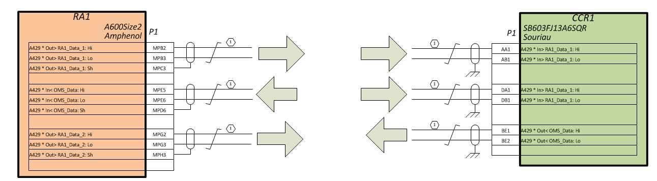
Fig. 1: dBricks Wiring Data Model
At the project level, device ports must be connected by the use of ‘buses’ entities. Based on pin assignment and port connection data, e.g. connection diagrams can be generated.
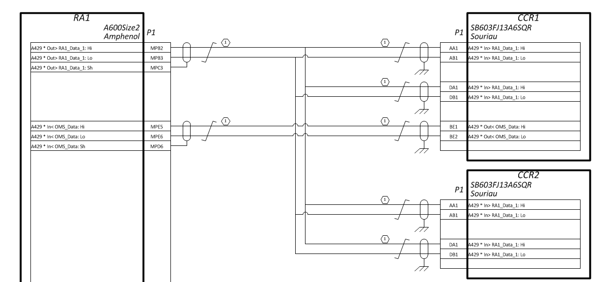
Fig. 2: Port Connections and Pin Allocations
In case of aircraft wiring, determination of device inner connections is followed by extensive work aimed to figure out actual implementation details: routing areas, technical connectors, wire branching points, etc. Since test benches are not intended for flight, their wiring layout can be significantly simplified. For more details see description of hardtware in the loop test benches design approach below. For now, let's just say that using dBricks and the approach described below, you can:
The second option is probably even more important than the first one: based on our experience, an aircraft model can face two to three dozen ‘major’ wiring configuration iterations even before certification.
Every electronic unit has collections of functions and port contents. Device functions define the purpose and information flows of the device. Each function describes one of the possible device purposes.
Each device in an equipment system has its own function. The function is determined by the purpose itself and the possibilities of interaction with functions of other devices. In the absence of a purpose, the device becomes unnecessary. In the absence of interaction with functions of other devices, the function should not be included in the system.
Functions may contain a collection of function parameters. As first approximation, each function parameter has the following properties:
Ports contents are definitions of how data is transferred between devices through information ports. The content structure depends significantly on the type of bus used for the transmission. Meanwhile, there are several properties common to all data transfer standards (bus types):
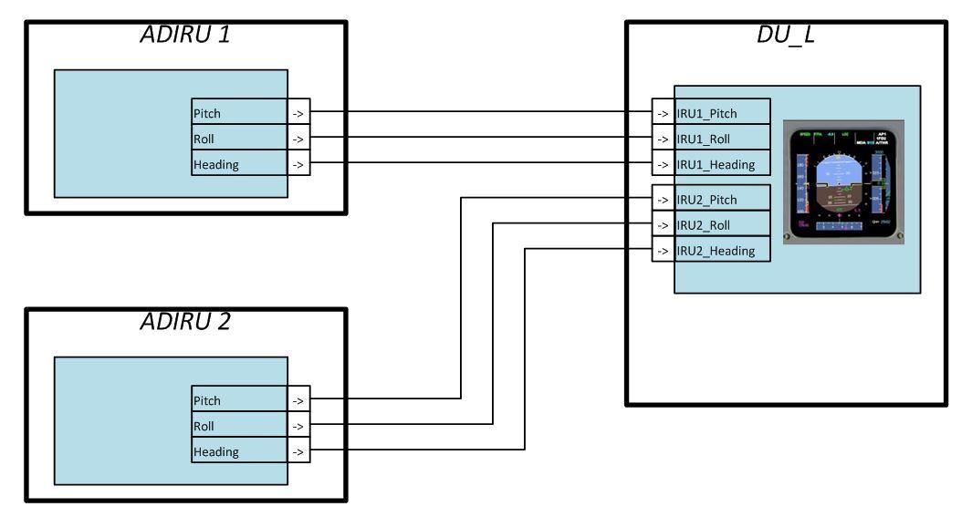
Fig. 3: Data Flow
ADS2 stands for Avionics Development System - 2nd Generation. It is a real-time test and simulation environment specifically designed for development, test, integration, and validation tasks in aerospace, space, and automotive applications provided by TechSAT Gmbh.
ADS2 system is essentially comprised of the following components:
A typical ADS2 system consists of mandatory standard components such as the ADS2 kernel software, optional standard components such as the I/O hardware selection and the corresponding drivers, and finally custom extensions and modules.
ADS2 systems typically consist of the following main components:
The above list illustrates that ADS2 can be easily scaled from small desktop systems to large distributed systems. Note that the classification does not imply a different software implementation. All systems use the same software and hardware. It’s critical to consider this at early rig development stages. Based on our experience, the need to change system configuration always arises at an inopportune moment during operation, so do not underestimate this.
The following diagram shows the main components of the ADS2 software package.
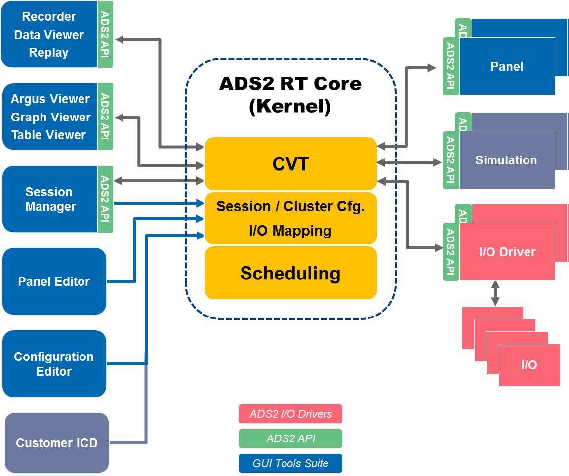
Fig. 4: ADS2 Software Architecture
The major components are:
Individual pieces of data that are used by various parts of the system and are exchanged between all different types of applications (user-provided applications as well as ADS2 internal applications) are defined in Current Value Tables (CVT). CVTs points are sets of process variables where each individual variable has a definition with a set of attributes that characterize the variable and reflect its intended use. CVTs and CVT points are the only means by which applications can exchange data between one another. CVT points are referred to by name throughout the entire system, so each point can only have a single definition at a given time. The attributes of a point are:
Besides the name given to a CVT point, it can also have additional aliases by which it can be referred to. Individual CVT points can be linked to one another in a way that a point A can be declared to be the source of a point B. This establishes a directed data path between these two points, thus whenever A is written also B is updated accordingly. In this case, the data types of A and B do not necessarily have to be the same; an implicit data conversion is performed (which may, however, result in loss of precision). Applications specify the data they consume and produce by means of CVT points, i.e. a set of points (respectively point names) as inputs and a set of points as outputs. This follows a typical publish/subscriber model of specifying the data interfaces of applications.
For the applications, functions of other applications are completely transparent, as well as it is transparent if other applications produce or consume the data, and what exactly they publish and subscribe to. They simply read from a point and write to a point. The ADS2 Core software takes care of transporting the data to where it is needed. When CVT points are exchanged, there is additional data besides the actual value that is transported and made available to applications: each data item carries along a timestamp that indicates when this data has been produced and a sequence number indicating how often it has been produced.
The ADS2 software itself uses CVTs to reflect certain system states and information. I/O driver applications provide certain predefined CVT points that are used uniformly in all I/O drivers to supply certain information to subscribing applications.
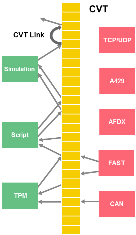
Fig. 5: Exchanging Data via CVT
The purpose of I/O maps is to decouple applications of any kind from direct access to I/O hardware, i.e. applications never have to deal with the intricacies necessary to actually perform hardware I/O (such as memory-mapped device access, interrupt handling, etc). Instead, I/O maps provide a means of mapping I/O channels, i.e. specific data items read from or written to I/O hardware to process variables, i.e. CVT points. Applications only have to deal with process variables. The mapping of hardware I/O resources onto process variables is accomplished through a configuration item called the I/O map. I/O channels can refer to any type of I/O handled by the I/O driver applications:
There are two major operations performed by the I/O drivers as part of processing the mapping definitions:
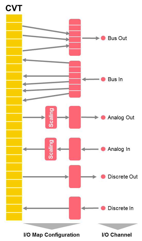
Fig. 6: Accessing hardware through I/O maps
The actual access to the I/O hardware is performed by I/O driver applications using the I/O map configuration information to transfer and convert the raw I/O data to CVT points and vice versa. Drivers are available for the following types of I/O devices:
The dBricks tool can generate the following configuration data needed to start ADS2:
The CVT points list is generated based on relevant equipment function parameters of dBricks (see dBricks Dataflow Data Model).
CVT points are generated for all input and output parameters of a function.
Example: The “Flight Warning Application” function of the unit “CentralComputer#1” has three input parameters and one output parameter:
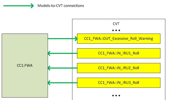
Fig. 7: CVT Configuration Example
CVT points links are generated based on connections between parameters of functions made in dBricks. For instance, the input parameter “In_IRU1_Roll” of “Flight Warning Application” is connected to the output parameter “Out_Roll_Angle” of function “Main” of unit “IRU1”:
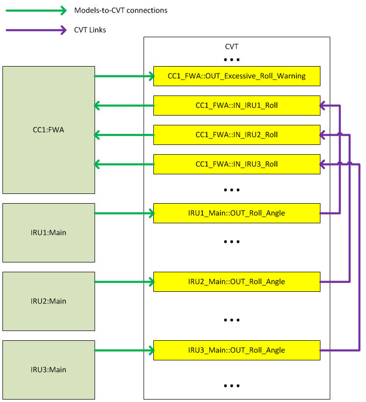
Fig. 8: Linking CVT Points
The I/O mapping is generated based on “ports contents” definitions. For instance, the parameter “Out_Roll_Angle” is transferred via ARINC429 label 325, coding type is BNR (fixed point), least significant bit is 11, size is 14 bits, most significant bit weight is 90, signed, refresh rate is 10ms. This description gives us enough information to create the I/O configuration file.

Fig. 9: EUT Connection Example
In conclusion, one can create the complete configuration of a large simulation system consisting of hundreds of models and I/O channels in less than an hour.
Other ways of generating CVT and CVT mapping are also available. The one mentioned above is frequently used and illustrates the approach well.
Simulink is a powerful software solution widely adopted by the aerospace industry. ADS2 offers convenient and simple sync with Simulink for the development of components’ computer models. When used together with dBricks for storing ICD data, it allows to create an integrated toolchain that significantly speeds up development and debugging processes.
The extensive use of Simulink together with ADS2 is possible because of the following facts:
This feature is needed because the C++ code that works in the Windows environment won’t work in the real-time Linux-based environment. So code that works in Windows should be replaced with code that works in Linux if we generate source code of the model for use in a real-time environment.
The process of developing real-time-ready models with Simulink is as follows:
Example. Let’s say we are developing our air data system model and we want to test it in closed loop together with EUT indication and real-time AC model. The air data system model gets airspeed data from the AC model, performs some actions, and sends it to PFD. To perform testing, we start the ADS2 environment with the real-time model of the AC dynamics and the real PFD screen. We move the throttle to maximum; AC begins to speed up. The Simulink model is connected to ADS2, so the Input speed parameter value increases as well. The Output airspeed signal goes back to ADS2, then it is converted to ARINC 429 and sent to PFD. So we can see the airspeed indication produced by the air data system model directly on the EUT PFD. That means we can create and test models using advanced Simulink GUI directly inside the powerful ADS2 environment. Certainly, Simulink running on Windows does not provide real-time functionality, but it is not needed for development.

Fig.10 Simulink-to-ADS2 connection example
Based on program needs test bench can have one, several or all following purposes:
We propose to use an ADS2-based solution as the simulation system since it provides:
The use of an ADS2-based solution will also reveal the full power of automated configuration generation using dBricks.
One of the most time-consuming processes of rig design is the configuration of the models’ interface and the configuration of the I/O boards. This bulky job can be done in an hour by using dBricks. The only thing that needs to be done is to link the simulated equipment ports to ADS2 I/O boards. Then all files are generated automatically and can be used as source configuration files. The typical simulation system of modern aircraft will consist of:
| # | Name | QTY | Comment |
| 1 | Real-time PC | 3 — 6 | Part of ADS2 solution. Runs ADS2-specific real-time operating system, Used for running compiled mathematical models of AC movement, equipment, etc., Can be used to add further interface cards needed to connect real avionics hardware. |
| 2 | Operator PC | 1 | Part of ADS2 solution. Runs Windows family operating system. Used for rig setup and control, Can be used for Simulink models testing as part of closed loop. |
| 3 | EVPS PC | 1 — 3 | Windows-based PC with good graphics adapter. Used for generation of pictures for EVPS. Connects to ADS2 data network via UDP packages. |
| 4 | FAST ADS2-controlled BOBs (Break Out Box) (FAST ADS2) | 1 — 10 | FAST is a Future Architecture System Testing a family of TechSAT-designed switching boards (BOBs) |
| 5 | I/O boards | 10-40 | A set of different interfaces I/O boards. The number of this board depends on which EUT will be installed on the Test Bench. Ordinarily this set includes following boards:
|
Some system suppliers are concerned about their know-how and refuse to supply data needed to correctly implement simulations of their systems sufficiently good to trick relevant onboard controllers. Engine suppliers are a good example. In that case, engine suppliers also provide simulators needed on the rig. These simulators are normally connected to the rig central simulation system via Ethernet or (in the worst case) some specific interfaces like “reflective memory”. In any case, ADS2 can support any interface.
The rig designer should pay attention that after-sales support is covered by the simulators’ delivery contract. As rig designer can’t modify or repair these simulators, a long-term (10-15 years) post-sales service and support should be ensured for externally supplied models (including upgrade, improvements, etc.). This support should also consider problems like spare parts cost, cost and time of repair, obsolescence management for installed equipment, availability of remote technical support, field rep visits, availability of customer support system, etc.
Rig wiring is one of the crucial parts. Approach and tools used for wiring development and manufacturing can significantly affect rig design and development schedule. We’re using an approach that has proved effective in several projects. Its basic principles are listed below:

Fig. 11: Assembled Wiring Harness
We suggest designing BOBs based on simple COTS, e.g. DIN-mounted WAGO 2002-1871 clamps with brake-out functionality and test ports.

Fig. 12: BOB based on COTS Components
The clamp solution allows for multiple connections by arranging WAGO clamps in groups as shown below:

Fig. 13: BOB arrangement example with WAGO сlamps
An example schematic of a generic signal path looks as follows:
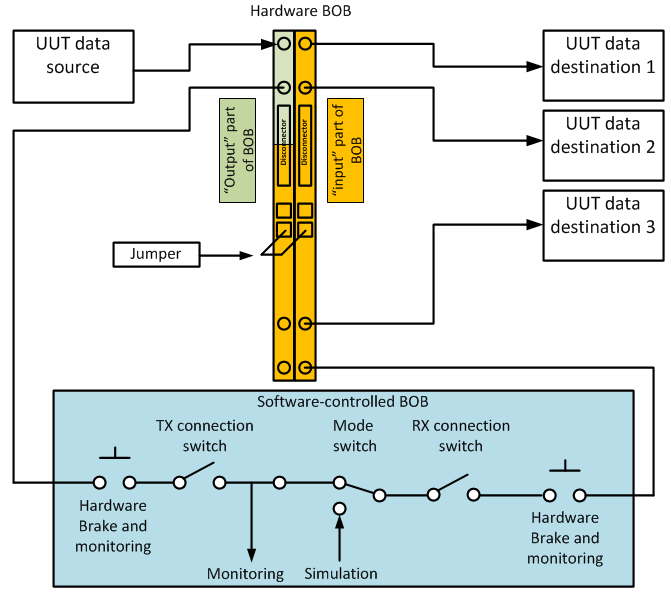
Fig. 14: Illustration of using HW BOB and SW-controlled BOB. UUT=Unit under test
Normally, rig wiring documentation development for airliner-sized aircraft takes 1-2 man-months of work.
Normally, the cockpit mockup should:
As the cockpit layout is subject to frequent changes, especially before a maiden flight, we start with the initial cockpit mockup and then proceed to the final one.
Initial Cockpit Mockup
The initial cockpit mockup (CM) can be designed based on the early designs of the layout. Minor changes in the cockpit layout between initial CM design and certification tests should not be addressed. The design of the initial CM should allow for access to rear panels and concealed parts of equipment. The picture below shows an example of the initial CM. Please note that all side panels can be easily removed, and overall design is modular.
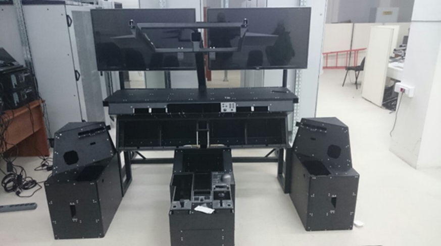
Fig. 15: Initial Cockpit Mockup
If possible, we recommend to avoid raised platform whenever possible. However, there are two rational reasons to use raised platform for CM:
We believe that CM raising height should be lowered if possible. This directly affects safety and ease of rig use. Stairs in rig room are more dangerous than ordinal stairs as people must walk around performing their duties so not so concentrated on walking as if they travel from one building to another. Stairs also prevent using carts, wheeled chairs can fall of it, etc.
Final Cockpit Mockup – AC certification aspects
The final cockpit mockup (FCM) should match the real one to meet the prerequisites of the certification tests. Depending on list of tests and authorities’ approach there might be a need to make additional “final” cockpit mockup that reproduce real cockpit. We believe that a solution could be to use the real part of the fuselage – previously used, but no longer needed, for other tests (e.g. “bird strike”, static strength) – with real equipment handling racks, pilot seats, etc. For example, the FCM initially used on the Sukhoi Superjet program was initially used for testing the new production line. It could not be used in real AC as not all formal manufacturing practices were fulfilled but it matched 100% needs of test rig.
Note: If you plan to use Final Cockpit Mockup as part to FTD Level 4 you should consider requirements that are covered in 4 CFR Part 60. Section 1b of Table B1A “Minimum FTD Requirements – General FTD Requirements QPS REQUIREMENTS” states: “The FTD must have equipment (e.g., instruments, panels, systems, circuit breakers, and controls) simulated sufficiently for the authorized training/checking events to be accomplished. The installed equipment must be located in a spatially correct location and may be in a flight deck or an open flight deck area. Additional equipment required for the authorized training/checking events must be available in the FTD, but may be located in a suitable location as near as practical to the spatially correct position. Actuation of equipment must replicate the appropriate function in the airplane. Fire axes, landing gear pins, and any similar purpose instruments need only be represented in silhouette.” We believe that even initial cockpit mockup meets these requirements.
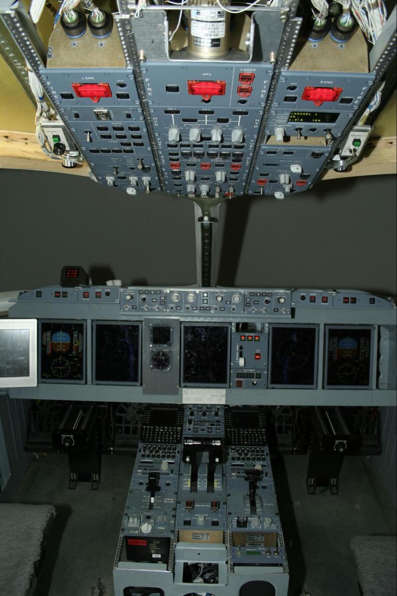
Fig. 16: SSJ-100 “Electronic Bird” test rig Cockpit Mockup
There are plenty of COTS EVPS solutions for flight training devices and test rigs. The types of EVPS can differ greatly from simple displays to high-end collimating systems. Two use cases may require using EVPS:
CFR 60 Table B1A section 6.a states: “The FTD may have a visual system, if desired, although it is not required. If a visual system is installed, it must meet the following criteria...” Thus, there is no need for EVPS for FTD Level 4 use at all. Even if EVPS is installed simple display-based EVPS will meet requirements stated in sections 6.a.1-6.a.7 CFR 60.
Most of certification tests are performed in the worst condition, that means instrumented flight rules and zero visibility. The only certification test type where the EVPS type really matters is visibility minimums evaluation. Performing these tests on the rig can save 20-40 test flights. Based on our experience, authorities did not require hi-end class EVPS system to make use Integrated Test Bench results as applicable mean of compliance. Anyway, certification authorities should be consulted if these tests are planned on the rig.
In real life engineers almost don’t use EVPS as they are focused on equipment behavior. Test pilots are normally satisfied with simple EVPS. Supporting press releases might be a use for EVPS.
Therefore, it makes sense to choose the mid-price solution of a cylindrical or spherical projection system as it provides:
We propose to use COTS telecommunication racks (server racks) for mounting an EUT that is normally installed outside the cockpit. The only problem with using them is cooling needed by some equipment. The problem can be solved in several ways:
PDS as described in proposal is a system that distributes EUT power. It replicates PDS used in AC.
Conversion of 115 Volts alternating current to 28 Volts direct current and 115 Volts 400 Hertz is not a problem. A lot of COTS devices are available. Thus our proposal does not focus on that work.
We propose to use the following approach:
The initial PDS mockup is made with COTS general use parts like WAGO clamps, relays, fuses, etc. All these parts are mounted on DIN rails or similar easy-access surfaces. Schematics for all connections should represent the proposed “real” PDS. Solid-state controllers can be used as is from the very beginning. Airborne PDS may not be available in time and is normally subject to many changes and updates, especially at the early stage of development. All these modifications can be completed much easier with an easily modified mockup than with an actual compact airborne power distribution device design.
Before the certification tests start, the PDS mockup can be replaced by real EUT PBS.
Based on program needs test bench can have one, several or all following purposes:
We propose to use ADS2-based solution for MIL test benches because of the same reasons as for HIL test benches. Typical simulation system of test bench consists of:
| # | Name | QTY | Comment |
| 1 | Real-time PC | 1 | Part of ADS2 solution.
|
| 2 | Operator PC | 1 | Part of ADS2 solution. Runs Windows family operating system.
Used for
|
| 3 | Control Panels and displays Displays simulation PCs | 2-3 | Part of ADS2 solution. Runs Windows family operating system. Identical to Operator PC but used for simulating displays and control panels |
| 4 | EVPS PC | 1 | Windows-based PC with good graphics adapter. Used for generation of pictures for EVPS. Connects to ADS2 data network via UDP packages |
Any test rig evolves as the project progresses. Therefore, nobody can propose the “complete” or “best” set of models to be developed. The good practice to keep a MIL-testing bench useful over the complete project timeline with affordable investments is to be flexible and try utilizing the Pareto-style approach. Nevertheless, we will try make an example of “initial” and an “advanced” set of models to exemplify ways to proceed.
The initial set of models in our example support the following activities:
During initial testing phase, there is no need to implement complex models of flight control electronics that include redundancy, reconfiguration, latency, etc. There is no need for testing complex applications like FMS either. Therefore, following preliminary list of models can be used:
| # | Model Name | Development Means | Hosting Part of Simulation System | Comment |
| 1 | AC dynamics model | Simulink | RTPC | Simple rigid AC model. Experience shows that XPlane-alike solutions are not accurate enough to build appropriate control laws. Simple Simulink model has to be based on careful numeric aerodynamics simulation joined with wind tunnel test results. |
| 2 | Atmosphere model | Simulink | RTPC | Includes standard atmosphere, wind simulation, simple anomalies simulation. |
| 3 | Simplified engine model | Simulink | RTPC | Direct link between TLA position and thrust. |
| 4 | Simplified flight control electronics | Simulink | RTPC | No redundancy, no signal quorum, no extra sensors (e.g. hydraulics) handling. |
| 5 | Simplified Flight control surfaces actuators | Simulink | RTPC | No dependency from power source (hydraulics and electricity), no feedback from aerodynamics forces |
| 6 | Simplified air data and attitude sensors | Simulink | RTPC | No redundancy, no errors models. |
| 7 | PFD simulation | C++ or Python | Display simulation PC | No redundancy, no health control, no reconfiguration, no navigation, no TAWS or TCAS data |
The “advanced” set of models should support the following activities:
As a result, the list of the final models is much longer. The list provided below is neither complete nor accurate. However, we believe the can give an impression of the work to be done.
Advanced list of models
| # | Model Name | Development Means | Hosting Part of Simulation System | Comment |
| 1 | AC dynamics model | Simulink | RTPC | |
| 2 | Atmosphere model | Simulink | RTPC | Includes standard atmosphere, wind simulation, simple anomalies simulation, FAA Advisory Circular-regulated anomalies. |
| 3 | Engine model | Simulink | RTPC | Includes mechanical part of engine. |
| 4 | Engine control electronics | Simulink | RTPC | Includes separate models for control and monitor channels, includes side-to-side monitor and control logics, considers that several sources of data available for any safety-critical function. |
| 5 | Flight control electronics | Simulink | RTPC | Includes separate models for control and monitor channels, includes side-to-side monitor and control logics, considers that several sources of data available for any safety-critical function, considers electrical power and hydraulic possible faults. |
| 6 | Flight control surfaces actuators | Simulink | RTPC | Dependent of all factors that can affect functionality: hydraulics and electric status. |
| 7 | Detailed avionics sensors | Simulink | RTPC | Separate models for separate sensors: ADC, IRU, GPS, VOR, DME, RA, ILS, etc. Contains possible failures simulation and measurement mistakes. |
| 8 | AC systems | Simulink | RTPC | Includes models of systems that can affect avionics behavior:Electric generation and distribution, APU, fuel, hydraulics, landing gear, nose wheel steering, doors control, fire protection, flight deck environment, etc. |
| 9 | AC systems electronics | Simulink | RTPC | Includes simulation of sensors, data concentrators, if any, and system controllers, if any. |
| 10 | Display simulation | C++ or Python | Display simulation PC | Normally consists of PFD, ND, FMS, TAWS, CAS, synoptic pages, CAS-messages, etc.Should consider real data flow, redundancy, reconfiguration, etc. |
| 11 | Control panels and signal lamps | C++ or Python | Display simulation PC | |
| 12 | Minor controls | C++ or Python | Display simulation PC | Includes landing gear lever, ground steering wheels, flap/slat control lever, spoilers control lever, etc. |
| 13 | Central computers | Simulink, C++ or Python | RTPC | Normally include simulation of following applications: FWS, DCA, SWS, CMS. |
For seamless transition between the initial and the advanced set of models, the following criteria for simulation systems should be met:
One more thing must be mentioned: if similar architecture is used for MIL and HIL test benches, many of the above-mentioned models are developed once and can be easily reused in any test benches.
The following approach is used for MIL rig cockpit mockup:
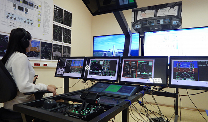
Fig. 17 Cockpit Mockup Concept
Any EVPS system needs from simulation environment continuous information of AC coordinates and Euler angles. Normally that data is sent using general use Ethernet via UDP packages. ADS2 environment can be easily configured for sending UDP packages with AC coordinates. That gives connectivity with virtually any EVPS solution.
Test bench design becomes simple when you understand why certain decisions are made. This information was compiled based on our years of work and experience in implementing successful and unsuccessful technical solutions.
You can request this text as a formal document in pdf format by the link